3-Way Bypass Valve with PTFE Diaphragm
Series TRVDT
Back to Summary
for Smooth, Sensitive Operation and the Ultimate in Corrosion Resistance
...with No Wetted Elastomers or Metals!

FEATURES:
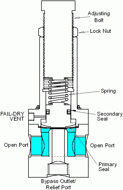
High flow relief/by-pass valve with 3-port design, ideal for applications where minimal footprint is required or where use of a piping tee is impractical. Valve has a straight-through flow pattern when closed. When set point is exceeded, the diaphragm is lifted off the center port, and excess flows "down" and out through the third port at the bottom of the valve.
For applications where a tee can be accommodated, a 2-port valve such as Series RVDT is usually preferred. If you are unsure which is right for your application, please contact our Technical Services Group at 973-256-3000.
-
Relief: protects systems and equipment from over-pressure/pressure surges.
- By-Pass: prevents pumps from "dead heading".
- Unique PTFE Diaphragm is excellent for use with highly aggressive liquids...and also provides the ultimate in contamination-free sealing.
- Rugged thermoplastic construction is ideal for a broad range of industrial applications.
- Available in 1/2", 3/4", 1" sizes. For other sizes consult factory.
- Relief setting is infinitely adjustable from 5 psi to 100 psi.
- Maximum inlet pressure is 150 psi.
- Large diaphragm area delivers more sensitivity and less pressure drop under flow conditions.
- Non-wetted u-cup seal provides a second isolation of the control spring; design includes patented Fail-Dry vent, a safety feature that provides visual warning of seal malfunction. This permits the valve to continue operation until a scheduled maintenance can be planned thereby avoiding a costly shutdown. Fail-Dry connection on Series TRVDT is 1/8" FNPT.
- Non-leaching feature of fluoropolymer diaphragm makes it ideal for use with ultra-purewater and concentrated etchants, as in the semiconductor industry.

Materials of Construction, Manufacturing Process & Quality Assurance:
Series TRVDT relief valves are available in GeonŽ PVC, Natural Polypropylene (virgin, unpigmented, unfilled PPL), KynarŽ PVDF and PTFE body materials. The wetted diaphragm is PTFE energized by a non-wetted Viton® diaphragm. Spring housing (completely non-wetted) is Geon PVC, but can be constructed of the wetted body material for a slightly higher cost. Springs (not in wetted area) are zinc-plated steel, external fasteners are stainless steel. Lock nut and adjusting screw are HDPE. If your environment is incompatible with any of the external materials, or you are interested in some other type of body material, options are available on quantity or special orders.Valve bodies are machined on state-of-the-art CNC lathes and machining centers. Parts are individually inspected prior to assembly. Valves are hand assembled, then inspected. Assembled valves are 100% individually tested (while pressurized) prior to shipment. All operations performed in our plant in Cedar Grove, NJ.
Optional Class 100 cleanroom cleaning and packing including wipe, rinse, Triton flush, nitrogen flush, DI rinse, nitrogen purge/dry, flourescent inspection, capping & 6 mil PE bag and heat seal available upon request. Performed at a certified remote location; priced per valve.
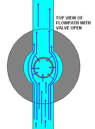
Illustration of Flow Path & Operation


Above, liquid pressure in the line is below the set pressure. The spring holds the primary seal tightly against the orifice at the top of the relief port. Liquid flows straight through the valve, "around" the closed relief port.
Below, liquid pressure has risen above the set pressure. The force of the liquid now exceeds the force of the spring; the pressure lifts the diaphragm off the relief port orifice, allowing liquid to flow down and through the relief port. In this way it "relieves" the pressure in the line.


Dimensions:

|
Size
|
A
|
B
|
C
|
D
|
| NPT |
in |
mm |
in |
mm |
in |
mm |
in |
mm |
| 1/2" |
2.5 |
63 |
1.48 |
37 |
4.4 |
112 |
1.38 |
35.1 |
| 3/4" |
3.0 |
76 |
2.81 |
71 |
5.5 |
140 |
1.66 |
42.3 |
| 1" |
3.5 |
83 |
3.0 |
76 |
7.65 |
195 |
1.94 |
49.4 |
Flow Characteristic at Overpressure
Curves show flow rate under laboratory conditions at various pressures exceeding the set point; i.e. flow characteristics with third port open.